Platforms
This page describes the use of the different platforms we support.
The general rule we apply for assigning IP addresses follows the following numbering order:
1 - Router
2 - Low-level computer (Raspberry Pi)
3 - High-level computer
4 - Additional component (e.g. Franka Arm)
5 - LiDAR
So for example, if we connect the Ouster LiDAR to the Lynx, we assign the Ouster with IP address 10.15.20.5.
Franka
Simulation Franka
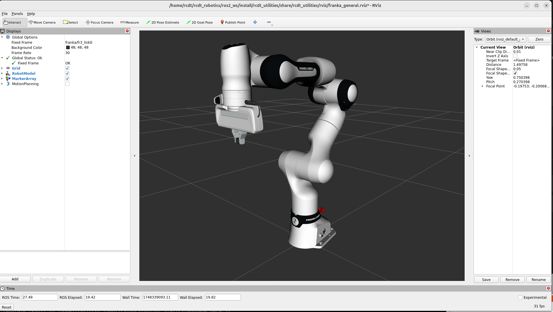
A Franka arm can be launched in simulation by creating a configuration with an Arm of type franka.
Hardware Franka
The robot needs to be connected with it’s control box.
Flip the switch on the control box to start the robot.
An ethernet cable should connect the control box with the network.
By default, we connect the control box with the router of the Panther.
The web interface can be reached on the statically assigned address:
10.15.20.4.
In the web-interface, settings can be changed and the joints can be (un)locked. The mode can also be changed to the required FCI mode.
UR
Simulation UR
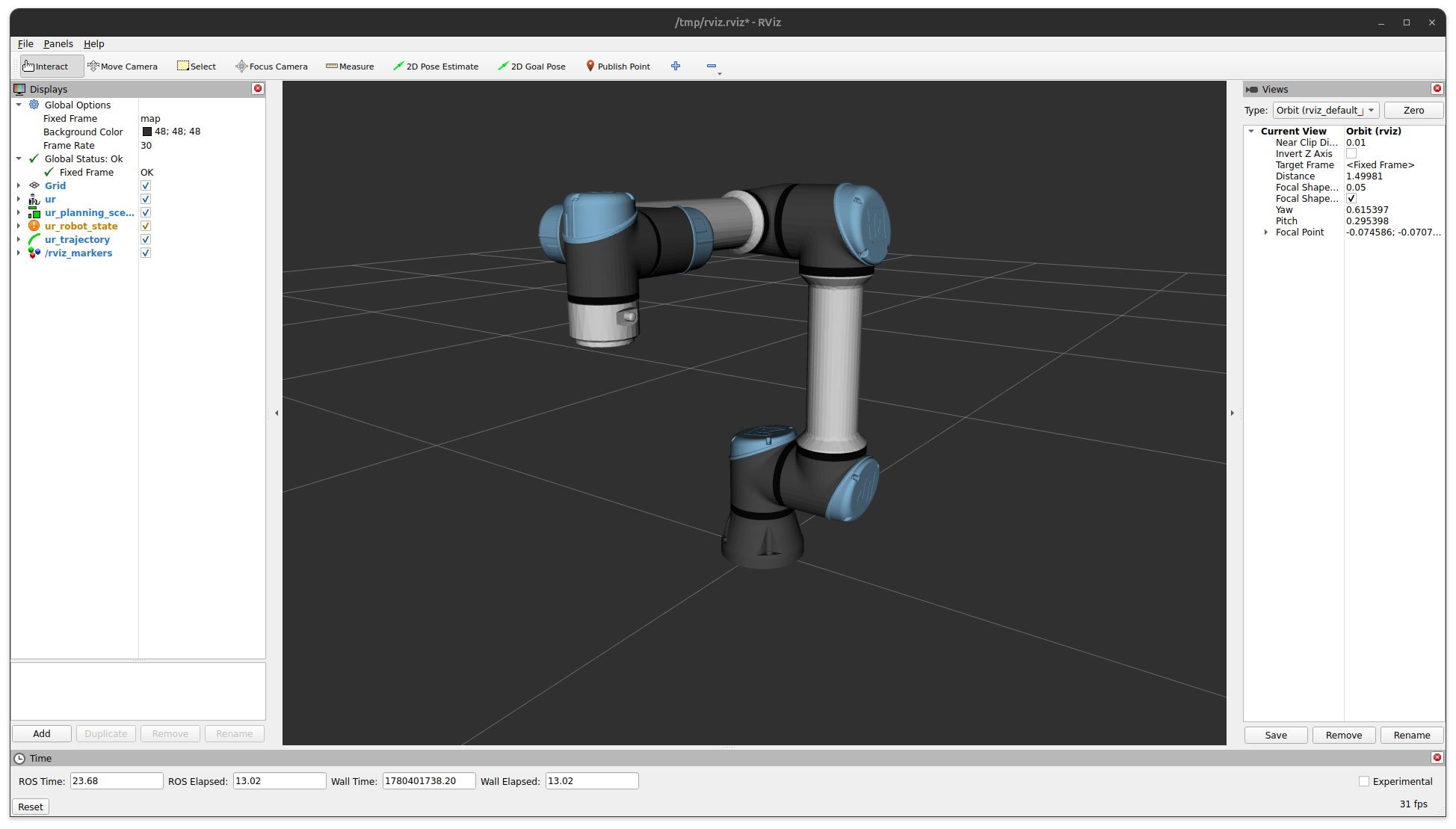
A UR arm can be launched in simulation by creating a configuration with an Arm of type ur.
Hardware UR
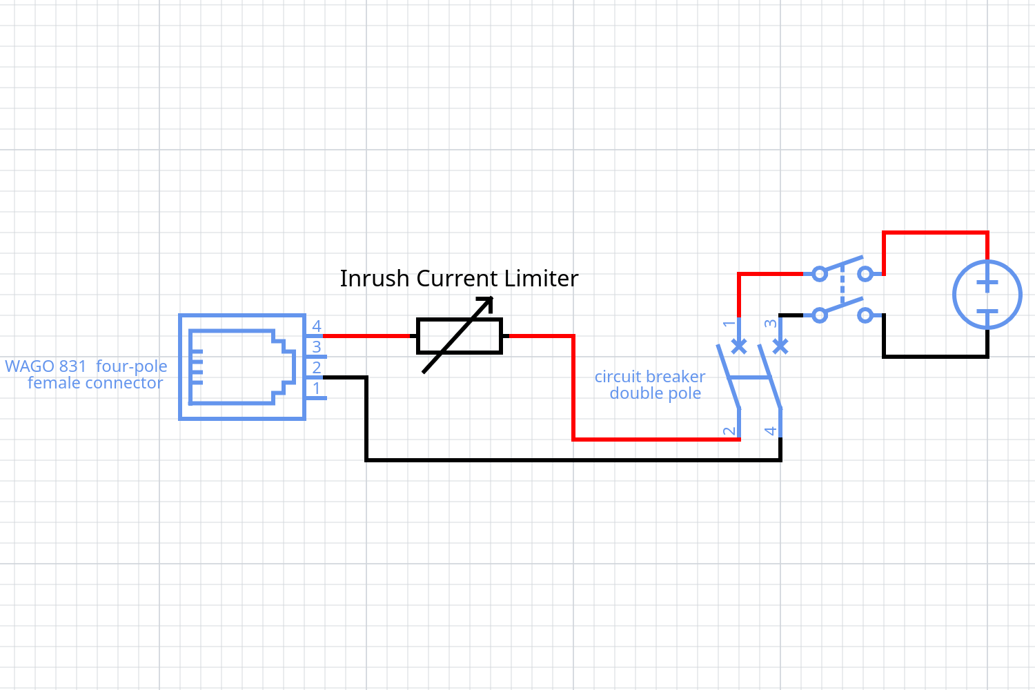
We have a UR7e arm with the OEM DC Control Box, so that it is possible to directly the power the UR arm with one of our vehicle platforms. This OEM version does not contain a Teach Pendant and a correct DC power supply is required. We built the following circuit to power the control box:
|
|
|---|
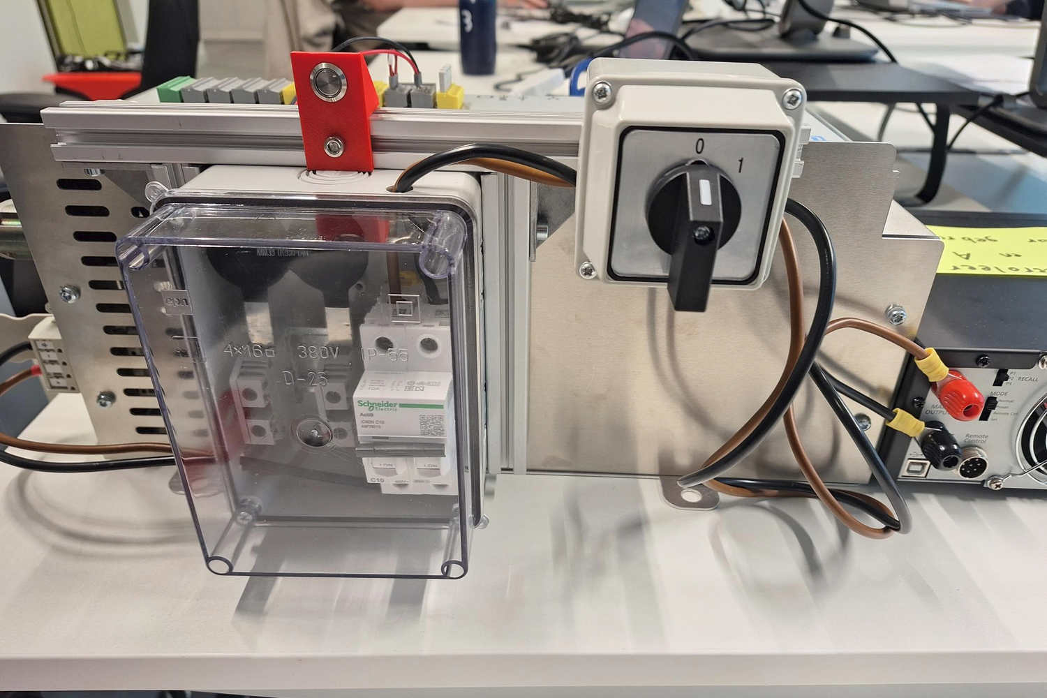
If desired, one can connect a display before startup using the mini display port, to visualize the control box interface. Now start the control box:
The robot needs to be connected with its control box.
Use the laboratory power supply or a vehicle platform to provide a DC source of 48V, 10A.
Flip the main switch on the control box (0 -> 1) to power the control box.
An ethernet cable should connect the control box with the network.
Start the control box by pressing the small button in the red mount.
The control box will start, which can take two minutes, indicated by a green led on the control box. Since remote control is enabled, the arm can be started directly from our code using headless mode:
Use a correct manual ip address for the host device to communicate with the control box (which has
172.16.0.2by default).You can test the connection using
pingand thealliander_robotics/alliander_ur/dashboard.pytool.Run a configuration of the UR arm, the arm should start automatically, indicated by a green led on the control box.
You can power off the arm and shutdown the control box using the
dashboard.pytool.
In case the arm has entered a protective stop:
Unlock using the
dashboard.pytool.Attach to the UR docker container and run
ros2 service call /ur/io_and_status_controller/resend_robot_program std_srvs/srv/Trigger {}.
Panther
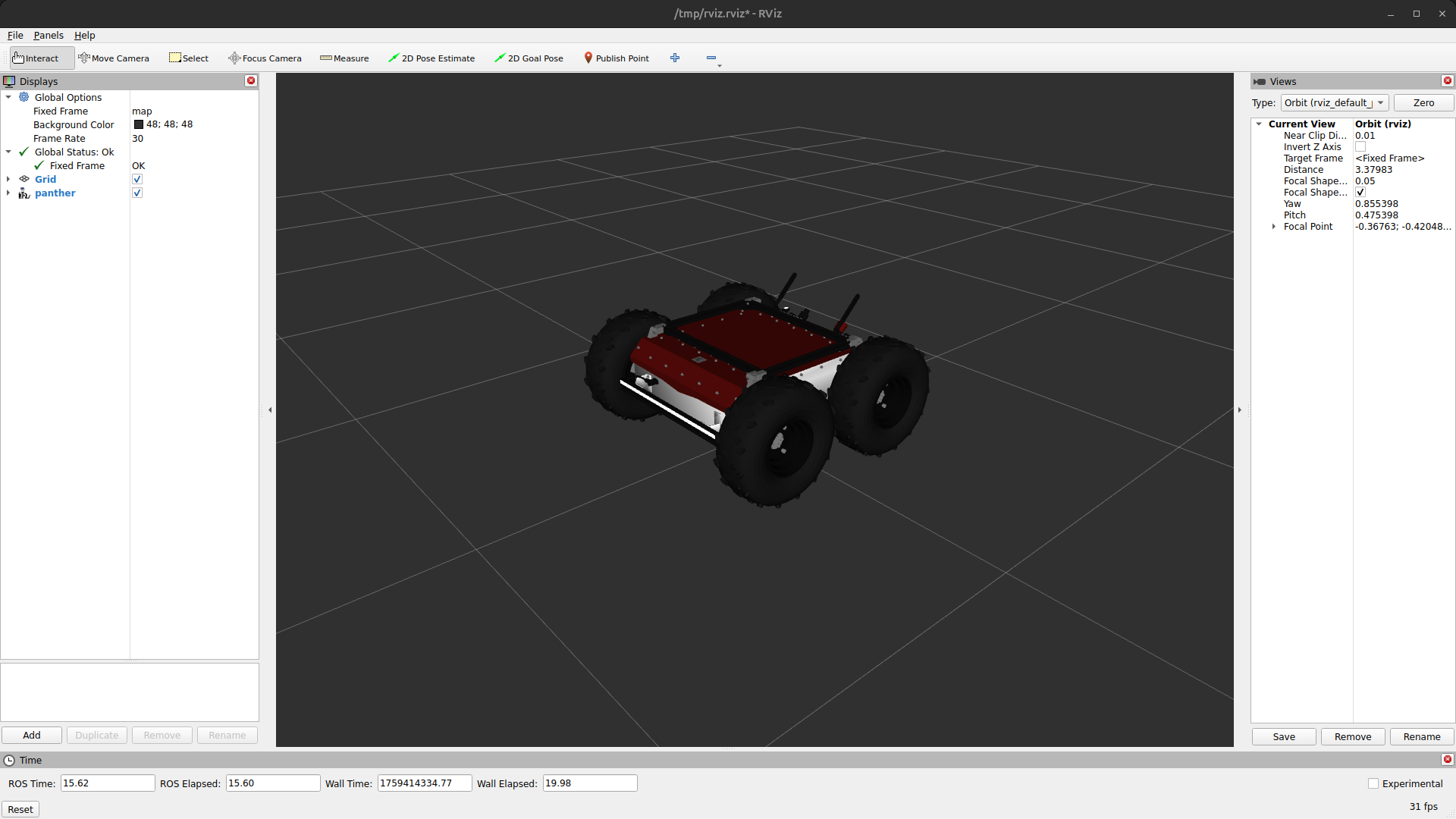
Simulation Panther
A Panther vehicle can be launched in simulation by creating a configuration with a Vehicle of type Panther. Note that the E-Stop is triggered by default and needs to be released before driving is possible. This can be done by a service call:
ros2 service call /panther/hardware/e_stop_reset std_srvs/srv/Trigger {}
Hardware Panther
Enable the battery (switch at the front of the robot).
Start the robot (press red power button).
Wait until the E_STOP animation is played
Release hardware stop (rotate red emergency button if it was pressed).
Start the Logitech gamepad:
press Logitech button.
press mode button if mode light is on (should be off).
put the switch at the back on X.
Remove the E_STOP by Left Trigger + A on the gamepad.
You can drive by pressing Left Button and use the two joysticks.
You can enable the E_STOP by pressing B.
See this for more information about gamepad control.
One can enable the high voltage system of the Panther (for example to power an Arm) using a service call:
ros2 service call /panther/hardware/aux_power_enable std_srvs/srv/SetBool "{data: true}"
The robot can be shut down as follows:
Shut down the robot (hold red button next to battery switch till it starts blinking).
Wait until all lights are off.
Disable the battery (switch at the front of the robot)
Configuration Panther
When the Panther is started, two WiFi networks (Panther_<serial_number> and Panther_5G_<serial_number>) should be available. One can connect with one of the WiFi networks or connect using a ethernet cable directly to the Teltonika. After connecting, it should be possible to ssh into all three computers.
Teltonika RUTX11:
This is an industrial router. The Raspberry Pi 4 and Lenovo ThinkStation P360 are connected to the Teltonika by Ethernet. Also the Velodyne Lidar and is connected to the Teltonika by Ethernet. A combo antenna (the black dome) is also connected, which enables the Teltonika to obtain a GPS location.
Raspberry Pi 4 :
The Raspberry Pi 4 is built in the front of the Panther and not directly accessible. Two Docker images are pre-installed: a docker image of the panther_ros repository and a docker image of the joy_to_twist repository. Both images are started automatically when the robot starts, as do all docker images installed on the Pi. The first image runs all the required software to use the robot, like motor control and led control. The second image enables gamepad control with the Logitech gamepad shipped with the robot, when the USB receiver is connected to the USB port at the front of the robot.
We have also cloned the nmea-gps-docker repository with a docker that enables use of GPS in ROS. This docker images gets started automatically as well when the the Panther starts. For more information about the use of this docker, see the Sensors section.
Lenovo ThinkStation P360
The Lenovo ThinkStation P360 is a powerful computer, used to handle the camera stream. We can run our docker image on this built in computer.
Lynx
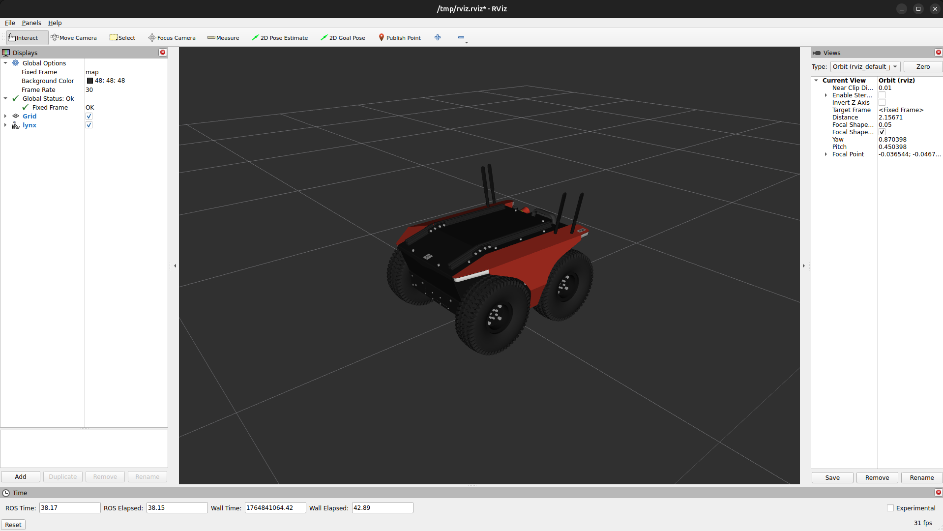
Simulation Lynx
A Lynx vehicle can be launched in simulation by creating a configuration with a Vehicle of type Lynx.
Hardware & Configuration Lynx
This section is equivalent to the Hardware Panther and Configuration Panther sections, except for the namespace here being lynx and the Lenovo ThinkStation P360 will be replaced with a different computer.
Ewellix
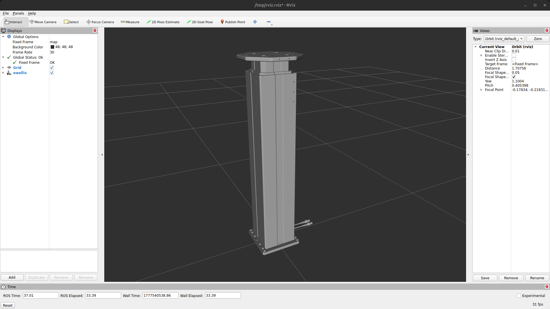
Simulation Ewellix
An Ewellix lift can be launched in simulation by creating a configuration with an Lift of type ewellix. One can control the lift by publish a command on the lift_position_controller/commands topic.
Hardware Ewellix
One can use an Ewellix lift by connecting it with the host device using USB. One can control the lift by publish a command on the lift_position_controller/commands topic.
Realsense
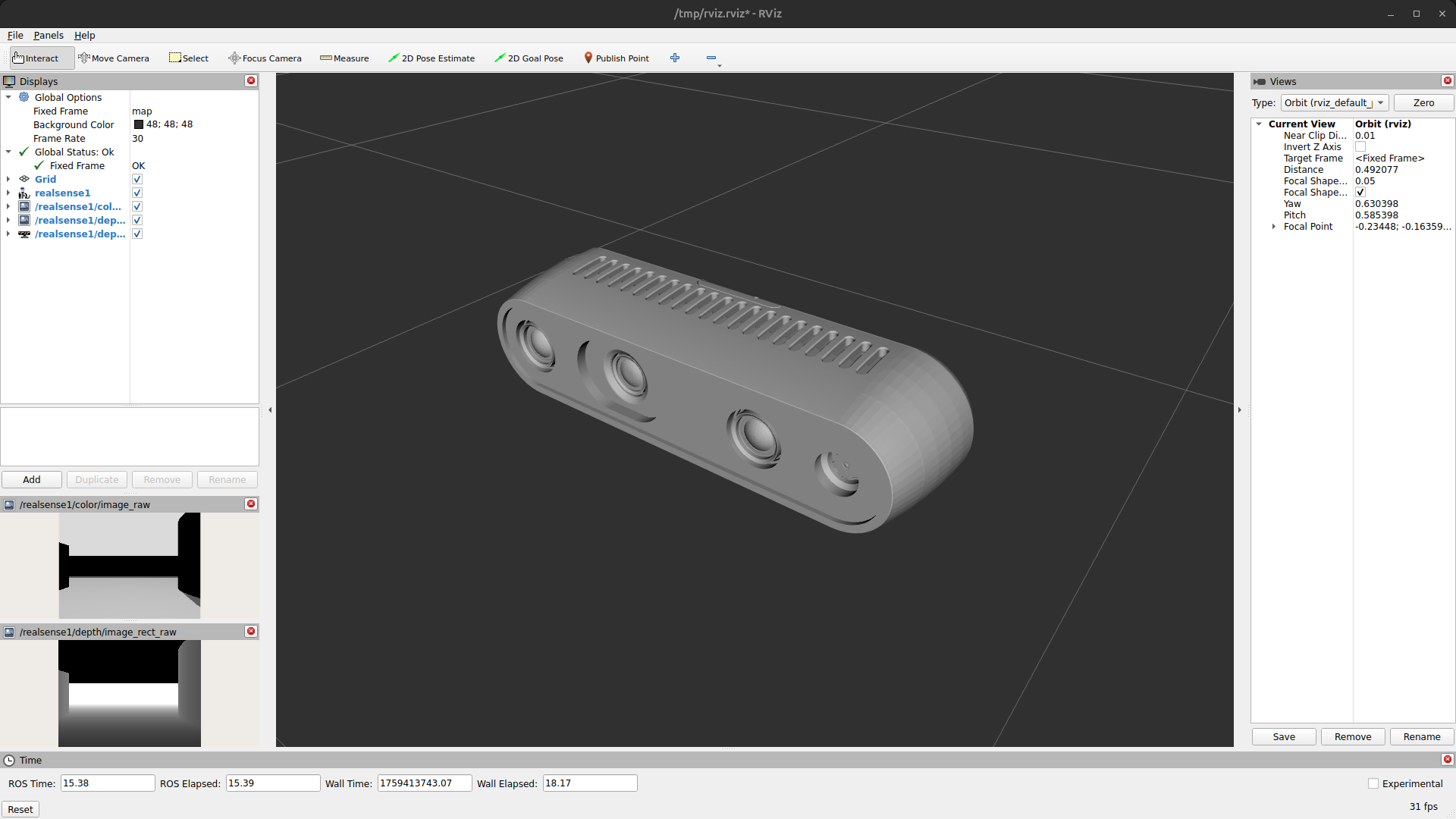
Simulation Realsense
A Realsense camera can be launched in simulation by creating a configuration with an Camera of type realsense.
Hardware Realsense
One can use a Realsense by connecting it with the host device using USB.
Seek Thermal
Simulation Seek Thermal
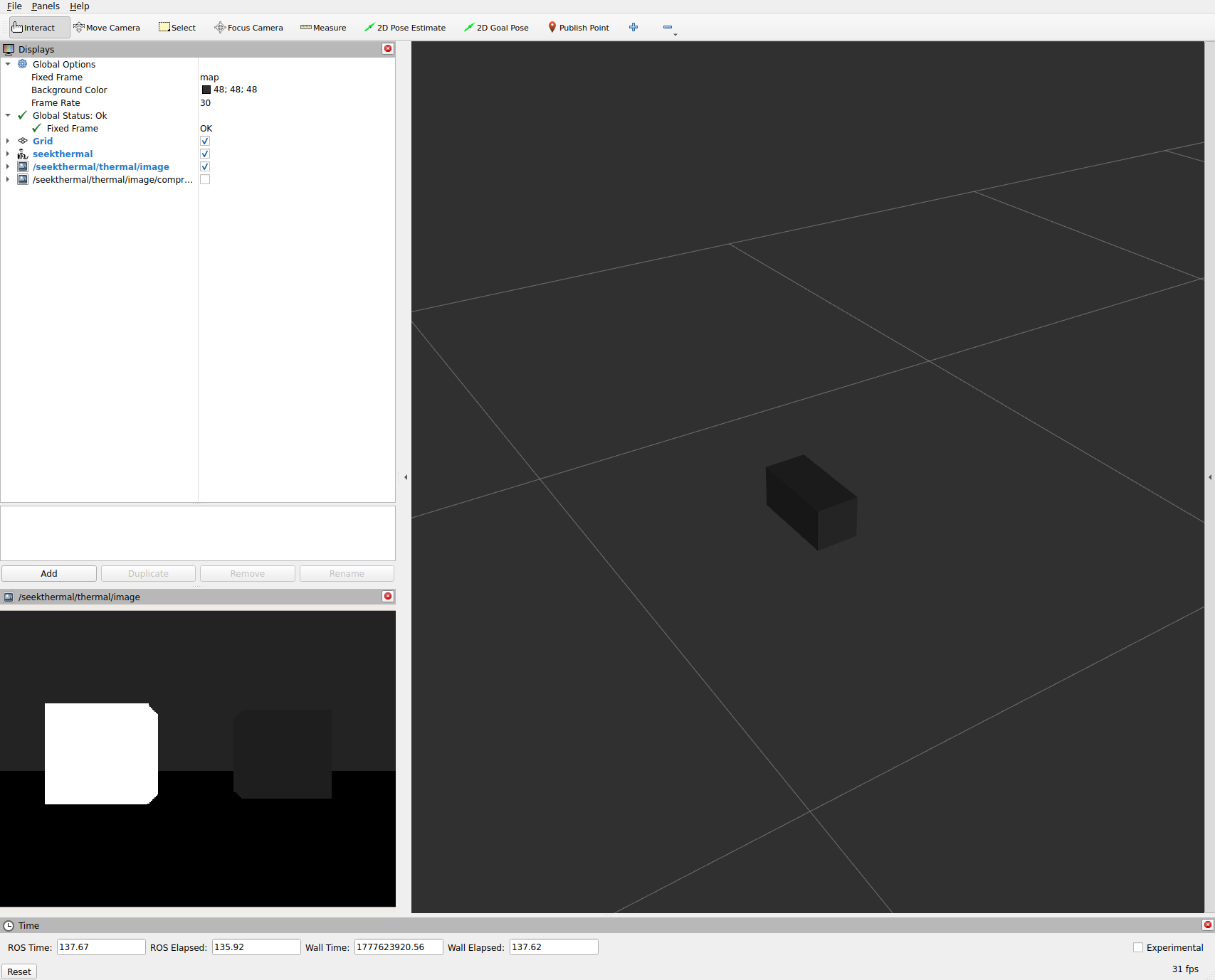
A Seek Thermal camera can be launched in simulation by creating a configuration with a ThermalCamera of type seekthermal.
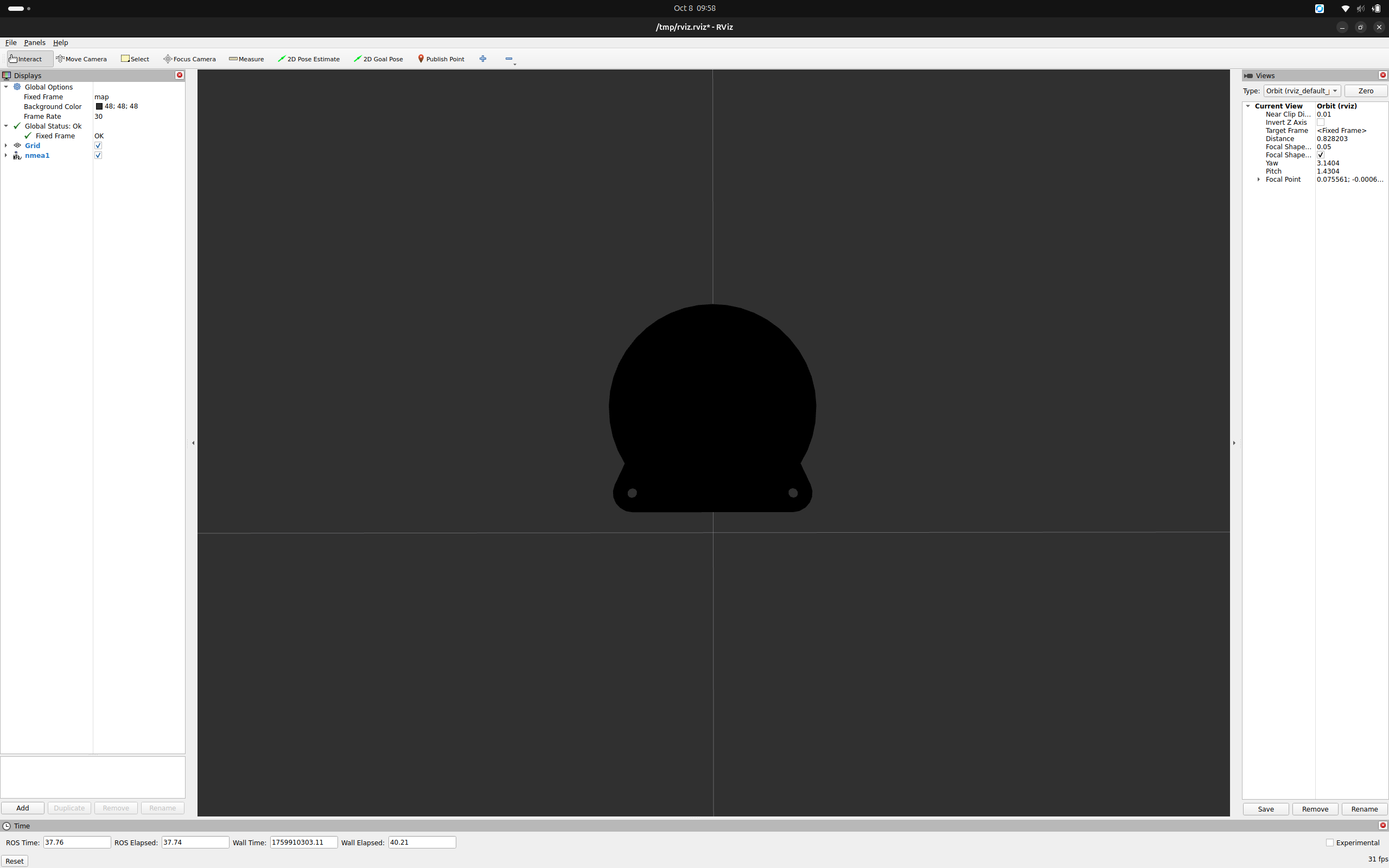
Hardware Seek Thermal
To use the Seek Thermal camera, connect it to a PoE injector’s OUT port. A PoE injector is shipped as an accessory with the G300, and can be plugged into a power socket. Connect the IN port to your device, then launch the alliander_seekthermal container. If you get a connection error, you may need to press the RESET pin on the G300 while it is connected to your device in order for the G300 to follow your device’s network rules.
ZED
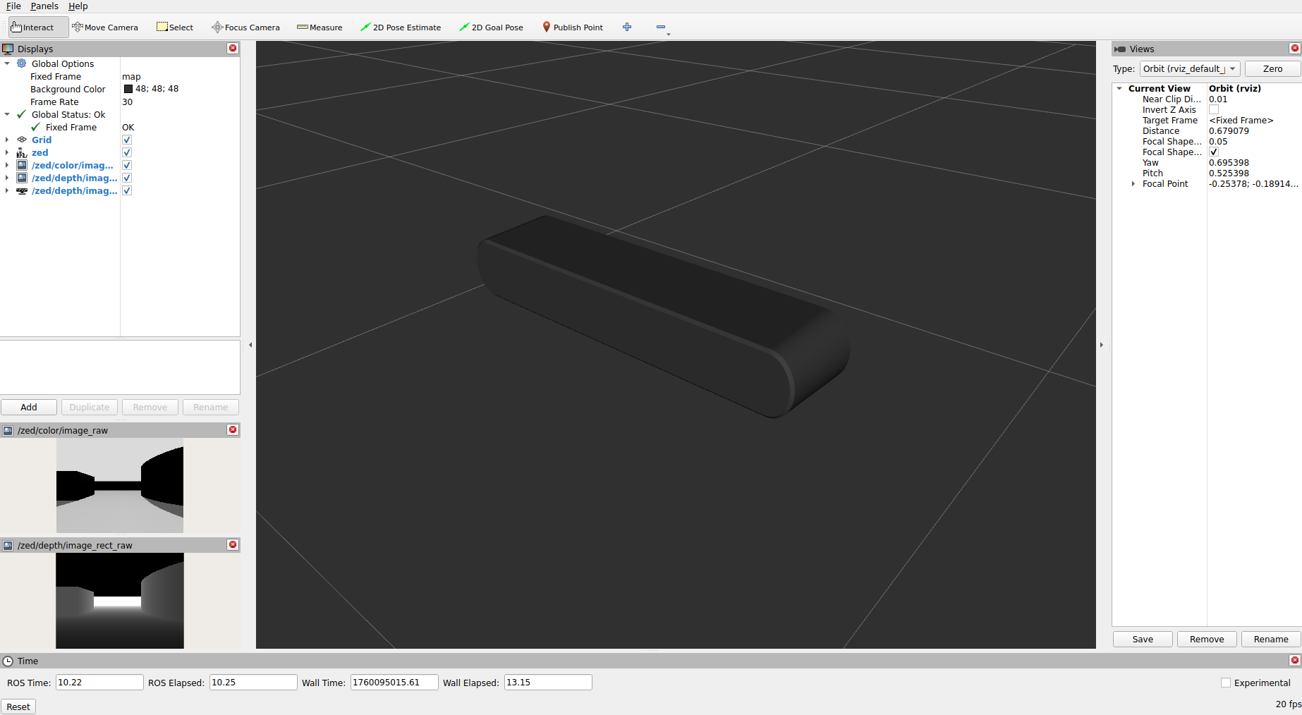
Simulation Zed
A ZED camera can be launched in simulation by creating a configuration with an Camera of type zed.
Hardware Zed
A ZED camera can be used by connecting it to the host device via USB. To allow non-root users to access the camera, UDEV rules must be installed on the host machine. The required script can be found here.
Ouster
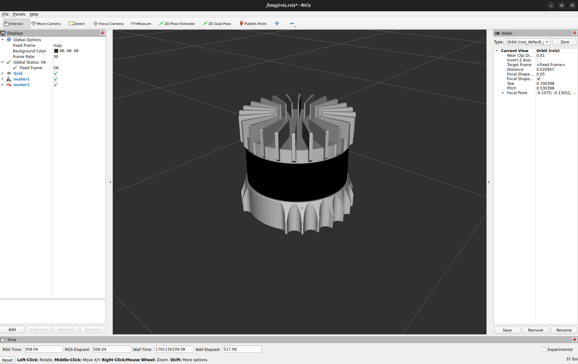
Simulation Ouster
An Ouster lidar can be launched in simulation by creating a configuration with a Lidar of type Ouster.
Hardware Ouster
Network settings:
When using the Ouster lidar, make sure that the IP-address of the host device (where the Ouster node is running) is set correctly in the settings of the Teltonika router. One can assign a static IP address to the Ouster via the Teltonika interface. In case of the Husarion vehicles, this interface is reachable via http://10.15.20.1/, and the static IP address should be set to 10.15.20.5 as number 5 is reserved for LiDARs.
Additionally, it is important to assign the correct UDP destination IP address for the Ouster LiDAR. This can both be done via the Ouster’s configuration interface at http://os-{serial_number}.local/, or it can be done via the launch file of the Ouster (ouster.launch.py in the alliander_ouster package).
Note: If the firewall is enabled in Ubuntu, communication with the LiDAR is most likely blocked. Unblock it by allowing the IP-address of the LiDAR:
sudo ufw allow to {IPv4_address}
sudo ufw allow from {IPv4_address}
ROS2 setup:
The Ouster driver runs as a LifeCycle node, meaning that once created, the node starts in an Unconfigured state. It needs to be configured and activated to start the driver.
Find all of the connected Ouster’s information at http://os-{serial_number}.local/, where the following parameters for the driver node can be found:
sensor_hostname: Dashboard > System Information > IPv4 (Remove the prefix length)udp_dest: Dashboard > System Status > Web Client Address
Velodyne
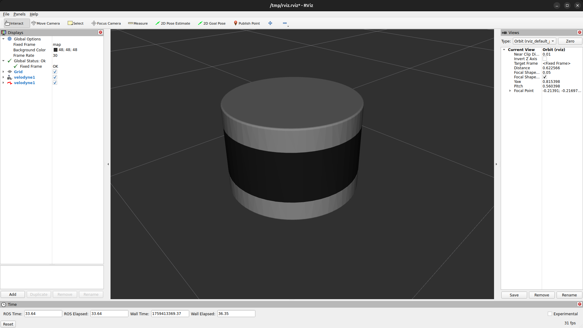
Simulation Velodyne
A Velodyne lidar can be launched in simulation by creating a configuration with a Lidar of type velodyne.
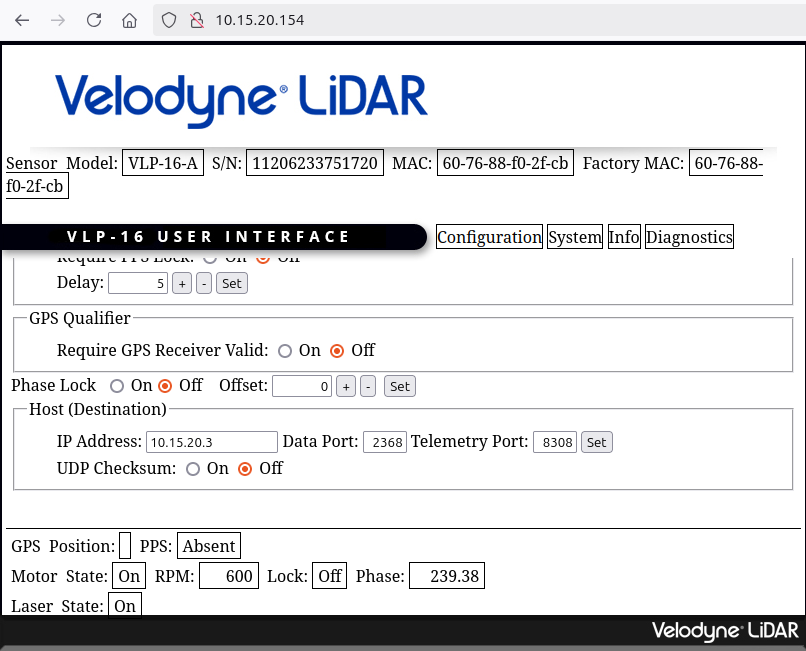
Hardware Velodyne
When using the Velodyne lidar, make sure that the IP-address of the host device (where the velodyne node is running) is set correctly in the settings. One can edit the settings of the velodyne using a web interface on it’s IP-adress.
|
|
|---|
Xsens IMU
Simulation Xsens
An Xsens IMU can be launched by creating a configuration with an IMU of type xsens.
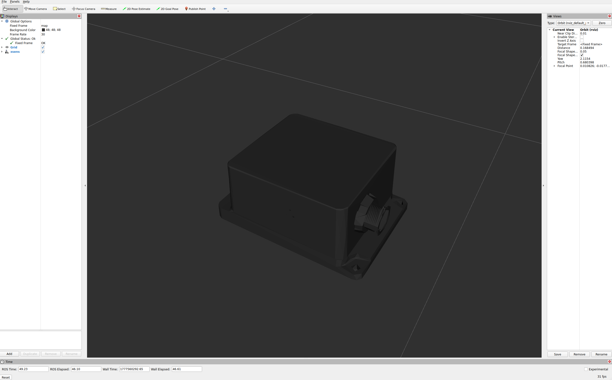
Hardware Xsens
When using the Xsens IMU, make sure that the IMU shows up on your device (use lsusb to check) and that the Docker container runs with privileged: true (standard in our repo).
Teltonika GPS
Simulation Teltonika
A Teltonika GPS can be launched in simulation by creating a configuration with an GPS of type teltonika.
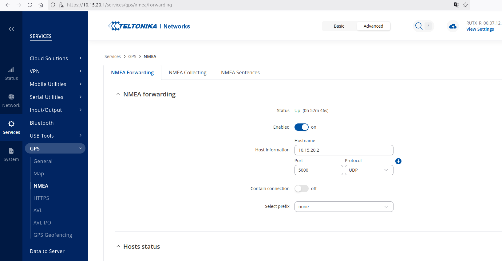
Hardware Teltonika
When using the Teltonika GPS, make sure that the IP-address of the host device (where the nmea node is running) is set correctly in the settings. One can edit the settings of the Teltonika using a web interface on it’s IP-adress.
Beamagine L3Cam
Simulation Beamagine
A Beamagine lidar can be launched in simulation by creating a configuration with the Beamagine type.
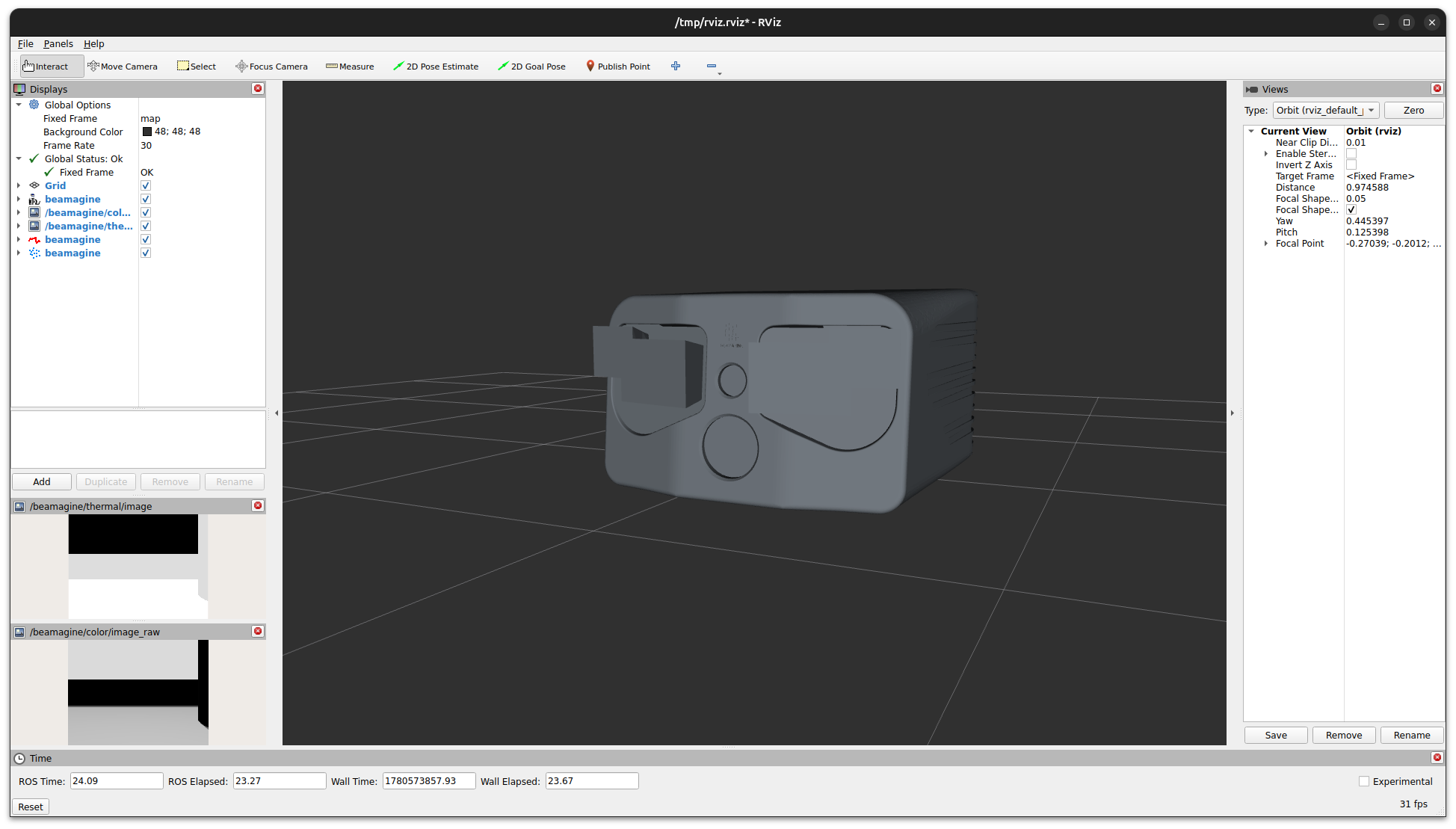
Hardware Beamagine
When using the Beamagine lidar, make sure that the network buffer sizes are increased. This can be checked using:
sudo sysctl 'net.core.rmem_max' # should be 268435456
sudo sysctl 'net.core.rmem_default' # should be 268435456
sudo sysctl 'net.core.netdev_max_backlog' # should be 5000
Update the buffer size with the following commands:
sudo sh -c "echo 'net.core.rmem_default=268435456' >> /etc/sysctl.conf"
sudo sh -c "echo 'net.core.rmem_max=268435456' >> /etc/sysctl.conf"
sudo sh -c "echo 'net.core.netdev_max_backlog=5000' >> /etc/sysctl.conf"
sudo sysctl -p