Model Description
What is switchgear?
Switchgear is a high-voltage electrical installation that distributes a large, incoming current flow over a distribution grid at the substation level. It is organized into bays, which are connected together with a busbar system, which distributes the load.
Switchgear installations may differ in their physical design, but generally consist of the same subcomponents, such as busbars, circuit breakers, disconnectors, current transformers, and similar equipment. These subcomponents are made from different materials, each with its own specific properties.
Parameters such as the rated voltage, nominal load, and short-circuit capacity are important when configuring a switchgear installation. These parameters, as well as other requirements for switchgear, are extensively described in IEC standards. For example, the temperature rise test, which is part of the type testing, is defined in the IEC standards. During this test, the installation is loaded at 100% of the nominal load, and the temperature must remain below the specified limit.
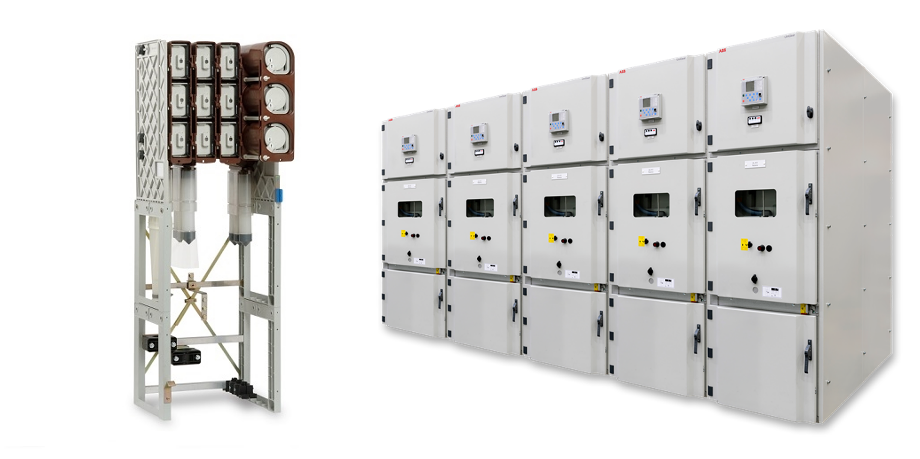
Examples of switchgear. Left: Eaton Magnefix (source: eaton.com). Right: ABB Unigear (source:new.abb.com).
Model Equation
The current model for assessing increased loading of switchgear is derived from the calculation methods described in IEC 62271‑306. These calculation methods provide guidelines for determining the loadability of switchgear by accounting for ambient temperature and heating time.
The equations described in the standard can be rewritten into the equation below, which is also known as Newton’s law of cooling. This formulation assumes that the rate of temperature change is proportional to the temperature difference between the component and its surroundings. In addition, it is assumed that the heat capacity is not temperature dependent.
where:
- \(\theta[t]\) - the temperature at time \(t\) in \(^{\circ}C\);
- \(\theta_{a}[t]\) - the ambient temperature at time \(t\);
- \(\Delta\theta_{100\%}\) - the temperature rise at nominal load over the ambient temperature in \(K\).
- \(I[t]\) - the current in \(A\) at time \(t\);
- \(S\) - the exponent (dimensionless);
- \(\tau\) - the thermal time constant in hours;
- \(dt\) - the time step size in hours.
This equation is implemented in the
switchgear_thermal_model.thermal_model.switchgear_temp
function. through a for loop, which loops over the point in time \(t\).