Realsense
We use a depth camera (Realsense D435) to sense the environment of the robot. This section describes how we use this camera on the real robot and in simulation.
Real robot
To use the camera with the real robot, we make use of the packages provided by realsense_ros. We can connect the camera via USB-C and launch the camera via ROS using the rs_launch file. In our rcdt_franka package, you can find a xacro file where we combine the description of the Franka arm and the Realsense camera.
Since the depth camera and rgb camera are placed next to each other, there is an offset between the images provided by both cameras. Fortunately, we can specify to align the depth image to the rgbd image and combine them into a single RGBD message in the rs_launch file.
Note
The depth image created by Realsense contains depth values in millimeters.
Simulation
We would also like to use a Realsense camera in simulation. To do this, we defined a xacro file where we use the description of the Realsense camera and add a Gazebo camera plugin. The description of the Realsense camera provides the following 4 frames:
|
|
|---|
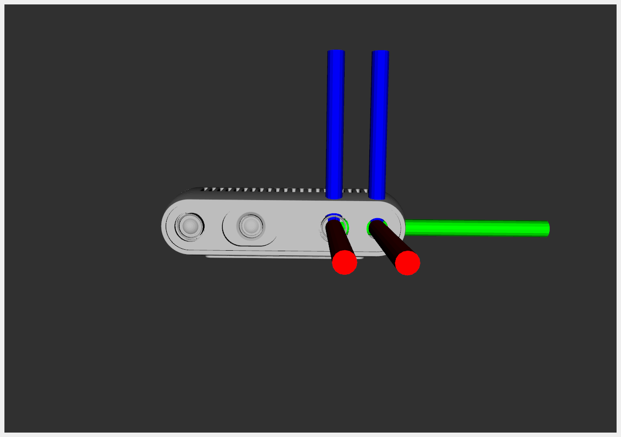
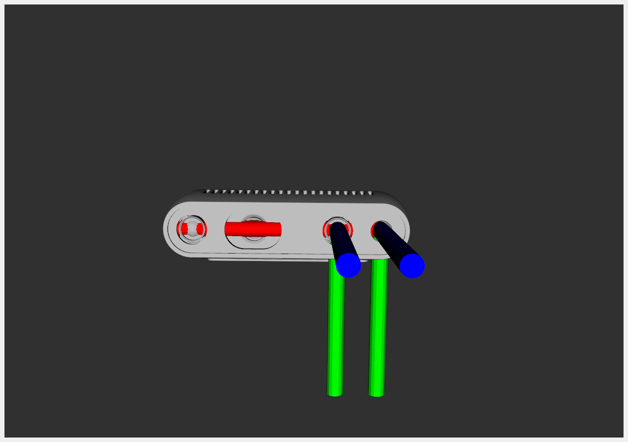
The left image shows the depth_frame (left) and color_frame (right).
The right image shows the depth_optical_frame (left) and color_optical_frame (right).
An optical frame is an orientated version of the normal frame.
The Gazebo camera plugin starts with the definition of a gazebo_reference to know where it should place the simulated camera hole. The camera will record the x-direction (red axis), so therefore this gazebo_reference should be the depth_frame or the color_frame.
Next, we define both a rgb sensor and a depth sensor. Both require an gz_frame_id, which is the frame in which the image is expressed. To simulate the Realsense camera correctly, the depth sensor should use the depth_optical_frame and the rgb sensor the color_optical_frame. However, using different frames for the two sensors would introduce an offset between the produced images, similar as with the real camera. To save the hassle of aligning the two images, we can avoid this offset by placing the two sensor at the same location in simulation. Therefore, we decided to use the color_frame as gazebo_reference and the color_optical_frame as gz_frame_id for both sensors.
Note
Also the resolution and field of view should be the same for both sensors in simulation to avoid an offset between the produced images. We have chosen to use the rgb sensor specifications for the depth sensor as well.
Note
The plugin generates a color and depth image (with depth values in meters). We created a node that bundles these to a RGBD image with depth values in millimeters, to achieve the same result as when using the real Realsense camera.
Camera offset
As mentioned before, the location of the camera with respect to the Franka arm is defined in the xacro file we created. Gazebo uses this xacro file to simulate the robot. Therefore, in simulation, the camera will always be placed exactly at the specified location. On the real robot, it can be difficult to place the camera exactly at the location specified in the xacro file. Therefore, the actual location can differ from where we think the camera is, which can result in detection errors.
In simulation, we have created our select_pick_location node, where the location of an object to pick is defined based on the depth image of the camera. Here we need to specify in which frame this pick location is defined. Since we choose to use the color_optical_frame for both sensors, this pick location is also expressed in the color_optical_frame. By using this correct frame, we can let the end-effector move above the detected object, which should result in a nicely centered position, as shown in the first of these three images:
|
|
|
|---|
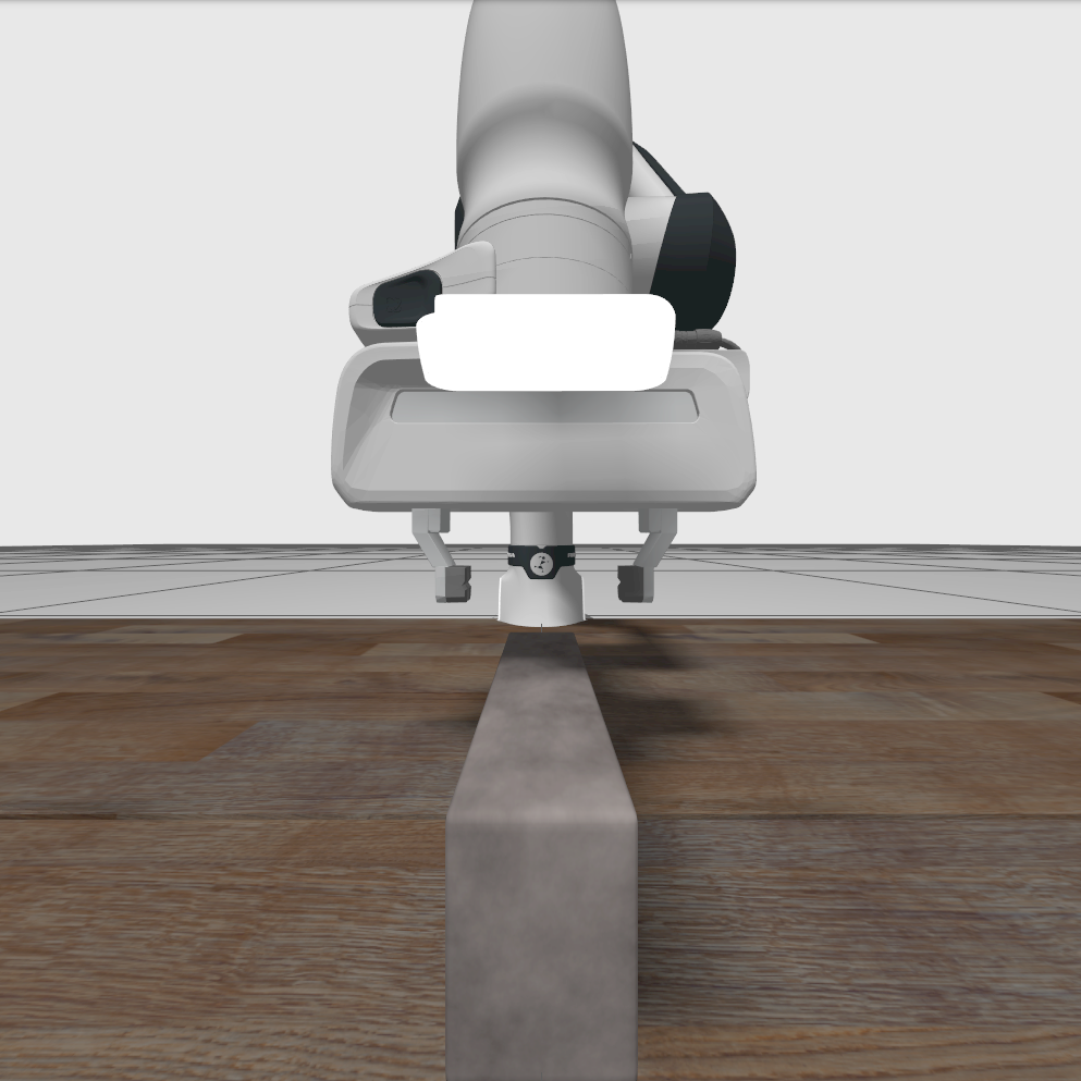
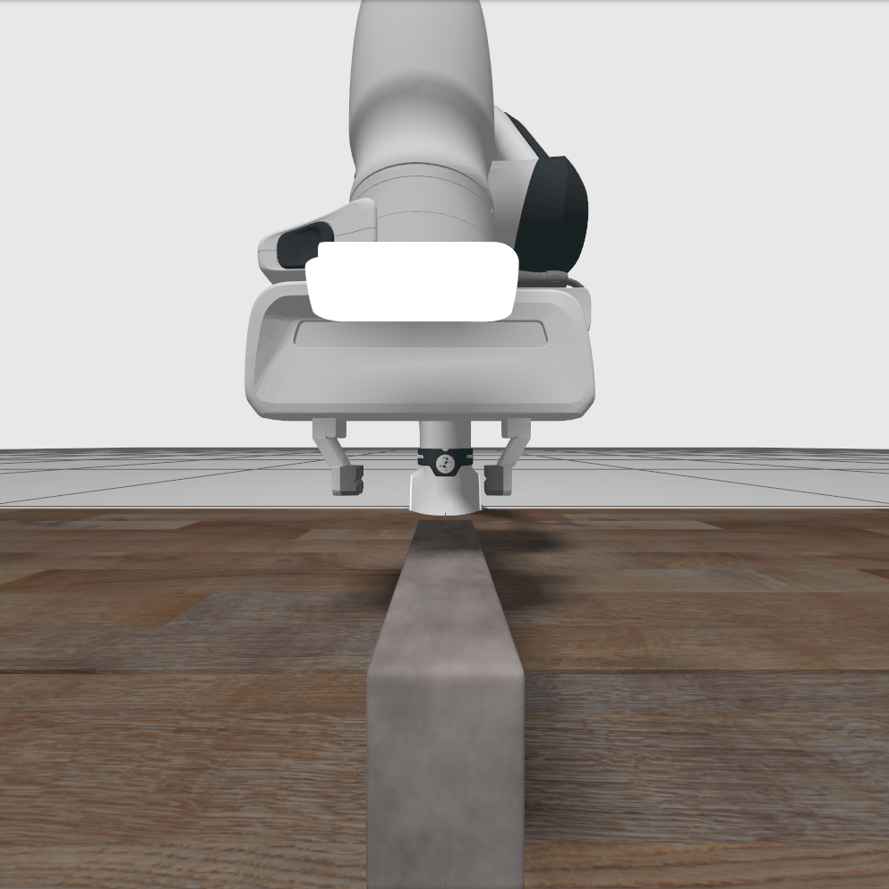
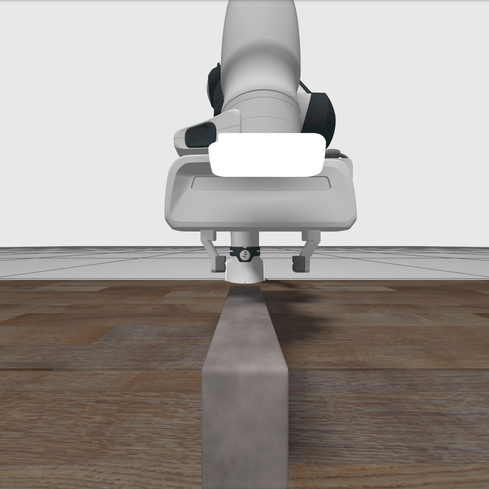
We can simulate a camera offset by expressing the pick location in the depth_optical_frame, while the simulated sensors are still working in the color_optical_frame. Since the depth_optical_frame is located slightly left from the color_optical_frame, the end_effector ends a bit too much to the left now, as shown in the second image. Finally, we can also define both simulated sensors in the depth_optical_frame, while expressing the pick location in the color_optical_frame. This time, the used frame is more to the right than the actual camera location, so the end-effector also ends too much to the right, as shown in the third image.
If the real robot moves the end-effector to detected objects with a consistent offset, the actual camera position might be different compared to the definition in the xacro file, just like we simulated in the images above.